- Free shipping for NZ Customers. All items are available in NZ warehouse
- +64 (0) 212576146
- [email protected]
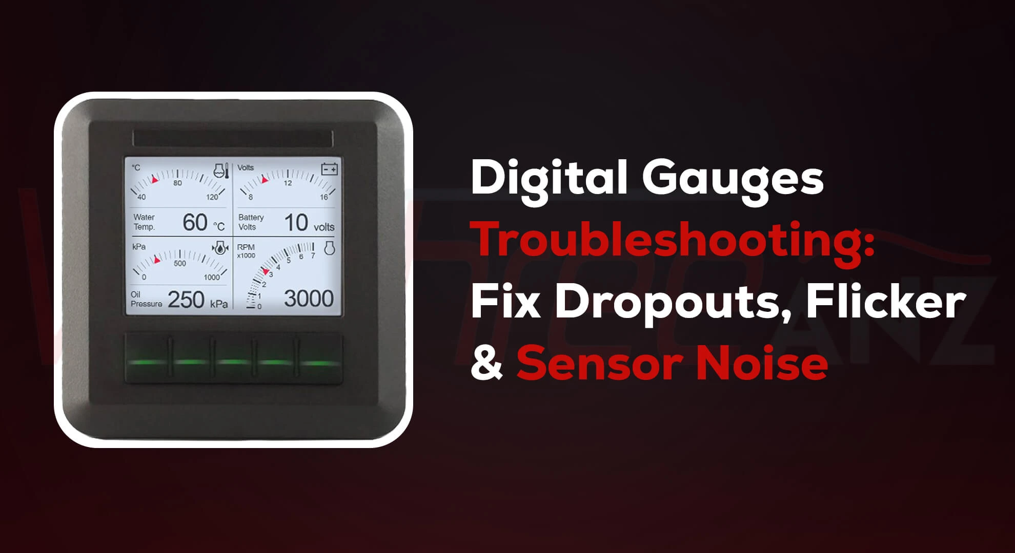
Digital Gauges Troubleshooting: Fix Dropouts, Flicker & Sensor Noise

Electrical Gauges Wiring 101: Safe Installations for Outboards & Inboards
August 30, 2025
Mechanical Gauges in Diesel Applications: Pulsation Damping & Vibration Mounts
September 17, 2025
Digital Gauges playing up?
Readings jump. Backlights flicker. Needles freeze. Ugh.
Good news: it’s often simple. Most issues come from earthing (grounding) and electrical noise. ⚡️
Below is a warm, no-jargon guide and a clear flowchart you can follow dockside or in the shed. Short steps. Plain language. Let’s get your Digital Gauges happy again. 🙂
Quick truth (so you don’t rip the dash out)
In cars and boats, dodgy earths cause a lot of weird gauge behaviour. Fix the earth and life gets better. It’s the same with networks like CAN bus and NMEA 2000. Proper termination and shielding stop the gremlins.
Tools you’ll want
- Multimeter (volts & ohms).
- Test light or dummy load.
- Small screwdriver, contact cleaner, zip ties.
The Diagnostic Flowchart (for noise & earthing)
Follow top to bottom. Stop when the fault clears.
1) Is the symptom global or just one gauge?- All gauges flicker or drop out → go to 2.
- Only one gauge noisy → skip to 4.
- Ignition on. Lights on. Load the system (blowers, wipers, sounder).
- Measure at the gauge’s positive and gauge’s earth pin.
- < 12.0 V on a 12 V system under light load? That’s low.
- Big dips when loads switch? Suspect wiring, fuses, or shared earth.
- Fix: clean terminals, crimp properly, run a dedicated feed and a star-earth to a negative bus. ABYC practice is to keep the DC grounding conductor non-current-carrying and not use it as a return.
- Put the multimeter black lead on battery negative, red lead on the gauge earth.
- Turn loads on.
- More than ~100–200 mV drop hints at a bad earth path. Clean, re-route, or upsize cables. ABYC guidance separates bonding/grounding from current-carrying returns to reduce stray currents.
- Yes → go to 5.
- No → go to 7.
- Power off. Measure resistance between CAN-H and CAN-L (or NMEA 2000 NET-H/NET-L) at any convenient plug.
- Reading near 60 Ω? Good (that means two 120 Ω terminators are present).
- Way off? Fix the ends: you need one 120 Ω terminator at each end of the backbone—no more, no less. This prevents reflections that look like “noise” and cause dropouts.
- Keep drop cables ≤ 6 m and total drops ≤ 78 m.
- Power the backbone from a single point (or isolated supplies) and keep the shield continuous, bonded to RF ground at one point only to avoid loops. These basics dramatically cut interference. If you’re outside these limits, you’ll see random disconnects and flicker.
- Run sensor grounds back to the same reference as the gauge, not to random chassis screws.
- Keep sender wires away from alternator and ignition leads.
- Use twisted pair and shield where you can; bond the shield at a single end to limit ground loops. (Ground loops and duplicated bonds are a common cause of gremlins.)
- Add ferrite beads or a common-mode choke on the signal harness (near the gauge).
- Move high-current devices (pumps, winches) off shared earth paths.
- Confirm the negative bus and bonding system are separate and compliant with marine practice.
Why flicker and dropouts happen
Weak earths make the Electronic gauge “see” a bouncing reference. The display or pointer jitters. Readings drift.
- CAN/NMEA reflections (wrong termination or long, messy stubs) scramble data packets. The network retries, then devices drop.
- Ground loops (multiple earth points) invite stray current and RF rubbish into your signals. One-point bonding and isolated network power keep things calm.
Mini checklist you can screenshot ✅
- Clean and remake gauge power and earth at a star negative bus.
- With power off, confirm ~60 Ω across CAN-H/L → you’ve got two good 120s.
- Keep NMEA 2000 drops ≤ 6 m; shield continuous; one-point RF ground.
- Separate bonding/grounding from current-carrying returns.
- Route sensor wires away from high-current and ignition wiring.
Keep it safe
Always isolate power before poking terminals. If you’re unsure about AC–DC bonding on a vessel, get a licensed marine sparkie. ABYC-style practice exists for good reasons.
Want help?
If you’d like, I can turn this flowchart into a printable, boat-specific checklist for your Digital Gauges. Or walk you through a live test plan. Flick me a message and tell me what you’re seeing. Let’s sort it. 🚤🛠️
FAQs
- If all gauges flicker or drop out → start with power/earth checks.
- If only one gauge is noisy → skip to sensor wiring and network checks for that device.
- On a 12 V system: < 12.0 V under light load is low.
- Big dips when loads switch → suspect wiring, fuses, or shared earths. Clean terminals, re-crimp properly, run a dedicated feed and a star-earth to a negative bus.
- > ~100–200 mV drop suggests a poor earth path. Clean connections, re-route, or upsize cables. Keep bonding/grounding separate from current-carrying returns (ABYC style).

